What is SPI Communication Protocol
Serial Peripheral Interface(SPI) is a common communication that used by many different devices. Some examples that use SPI to communicate with microcontrollers are:
- SD card modules
- RFID card reader modules
- 2.4 GHz wireless transmitter/receivers modules
Benefits To Using SPI
A key advantage of using SPI is its ability to transfer data without interruptions. Data can be transmitted or received as a continuous stream, with no fixed bit limits. In contrast, protocols like I2C (Inter-Integrated Circuit) and UART (Universal Asynchronous Receiver-Transmitter) transmit data in packets with a specific bit length. Each packet requires defined start and stop conditions, causing interruptions during transmission.
How SPI Works
Devices communicating via SPI are in a master-slave relationship. The master is the controlling device (usually a microcontroller), while the slave (usually a sensor, display, or memory chip) takes instruction from the master. The simplest configuration of SPI is a single master, single slave system, but one master can control more than one slave.
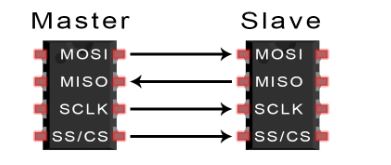
- MOSI (Master Output/Slave Input): Line for the master to send data to the slave.
- MISO (Master Input/Slave Output): Line for the slave to send data to the master.
- SCLK (Clock): Line for the clock signal
- SS/CS (Slave Select/Chip Select): Line for the master to select which slave to send data to.
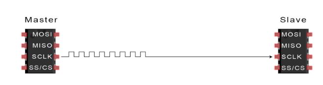
The Clock
In SPI communication, the clock signal synchronizes the transfer of data from the master to the slave, with one bit transmitted per clock cycle, making the data transfer speed dependent on the clock frequency. As a synchronous communication protocol, SPI requires the master to initiate communication by configuring and generating the clock signal. Unlike SPI, asynchronous protocols like UART rely on a pre-configured baud rate instead of a clock signal to manage data transmission timing. SPI's clock signal behavior can be adjusted using clock polarity and clock phase, which together determine when data bits are output and sampled. Clock polarity specifies whether bits are output and sampled on the rising or falling edge of the clock cycle, while clock phase defines whether these actions occur on the first or second edge, regardless of its direction.
MOSI And MISO
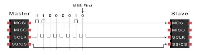
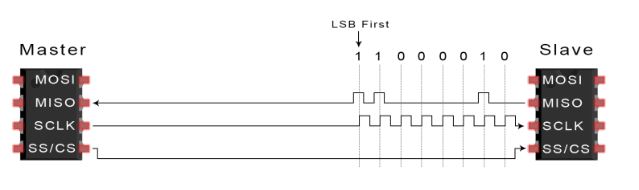
The master sends data to the slave bit by bit, in serial through the MOSI line. The slave receives the data sent from the master at the MOSI pin. Data sent from the master to the slave is usually sent with the most significant bit first. The slave can also send data back to the master through the MISO line in serial. The data sent from the slave back to the master is usually sent with the least significant bit first.
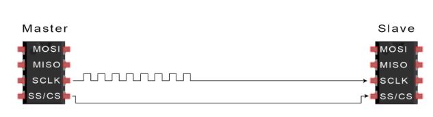
Slave Select
The master selects a specific slave to communicate with by setting the slave's Chip Select (CS) or Slave Select (SS) line to a low voltage level, while the line remains at a high voltage level in the idle, non-transmitting state. Multiple CS/SS pins on the master enable multiple slaves to be wired in parallel, but if only one CS/SS pin is available, multiple slaves can still be connected through daisy-chaining.
Steps Of SPI Data Transmission
- Step 1: The master outputs the clock signal
- Step 2: The master switches the SS/CS pin to a low voltage state, which activates the slave
- Step 3: The master sends the data one bit at a time to the slave along the MOSI line. The slave reads the bits as they are received
- Step 4: If a response is needed, the slave returns data one bit at a time to the master along the MISO line. The master reads the bits as they are received
Advantages And Disadvantages Of SPI
Advantages
- No start and stop bits, so the data can be streamed continuously without interruption
- No complicated slave addressing system like I2C
- Higher data transfer rate than I2C (almost twice as fast)
- Separate MISO and MOSI lines, so data can be sent and received at the same time
Disadvantages
- Uses four wires (I2C and UARTs use two)
- No acknowledgement that the data has been successfully received (I2C has this)
- No form of error checking like the parity bit in UART
- Only allows for a single master